
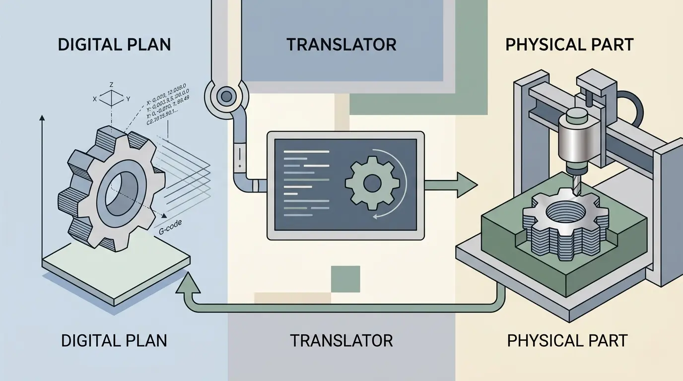
The phrase “CNC slicer” causes confusion because it sounds reasonable in several different digital-manufacturing contexts but does not point cleanly to one standard industrial tool. One buyer may mean a true 3D-printing slicer. Another may mean CAM software for a router or mill. A third may mean nesting software for sheet optimization. In some shops the term gets stretched even further to include machine senders or workflow utilities that prepare files for a specific device.
If that ambiguity is not resolved early, the team can waste hours trialing the wrong software category altogether. That is why this topic is less about one product and more about language discipline. In most subtractive CNC environments, the useful terms are CAM, nesting software, post-processing, or machine-preparation software rather than slicer. In additive manufacturing, slicer is a normal and correct term because the software converts a 3D model into layers for printing.
So the first job is not to choose a slicer. The first job is to identify what output the machine actually needs.
Start by Naming the Output, Not the Marketing Label
The fastest way to resolve the term is to stop asking what the software is called and ask what the machine physically does. Does it print material layer by layer? Does it remove material with a cutter? Does it optimize parts across a full sheet? Does it mainly need job transfer and controller-specific formatting?
Once the output is clear, most of the confusion disappears. The wrong software category only stays alive when the shop lets a vague label do the thinking.
That is why good teams do not begin with “Which slicer should we buy?” They begin with “What kind of instructions does our machine actually need?” That question narrows the field much faster than generic software browsing.
The Same Word Gets Used for Very Different Software Jobs
In real-world searches, “CNC slicer” usually collapses into several different intents that only sound similar on the surface.
| What the User Usually Means | What the Software Actually Does | Where the Term Fits Best |
|---|---|---|
| 3D-printing preparation | Converts a 3D model into layers, support logic, and print instructions | True slicer |
| Router or mill programming | Converts geometry into cutter-based toolpaths and machine logic | CAM software |
| Sheet optimization for panels | Places parts efficiently on material and often coordinates cutting order | Nesting software |
| Vendor-specific send or prep utility | Transfers, formats, or queues data for one machine workflow | Machine utility, sender, or post-related tool |
These are not small variations of the same product type. They solve different manufacturing problems and assume different process logic.
A True Slicer Belongs to Additive Manufacturing
In additive manufacturing, slicer is the correct term. The software takes a 3D model and turns it into layer-by-layer print instructions. It determines how the part is built rather than how material is removed.
Typical slicer decisions include:
- Layer height.
- Infill strategy.
- Wall count.
- Support generation.
- Build orientation.
- Print speed and temperature behavior.
Those are all valid and necessary questions for a print workflow. They are not the core questions of a router, mill, drilling, or sheet-cutting process. That is the first place many mixed-manufacturing teams go wrong. They carry additive vocabulary into subtractive work and then wonder why the software comparison feels wrong from the start.
If the machine does not build the part in stacked layers, the shop should already be suspicious of the word slicer.
Subtractive CNC Usually Wants CAM, Not a Slicer
In router, mill, and machining workflows, the correct software discussion usually begins with CAM. CAM software converts geometry into toolpaths based on cutter type, material-removal strategy, spindle behavior, workholding, machine limits, and postprocessor needs.
That means the software is deciding things like:
- Tool selection.
- Stepdown and stepover.
- Lead-in and lead-out behavior.
- Pocketing and profiling logic.
- Drilling cycles.
- Roughing and finishing sequence.
- Safe entry and exit motion.
That is why subtractive CNC shops usually do not need a slicer in the additive sense. They need the right CAM environment and, in some sheet-processing applications, nesting logic on top of it. Pandaxis already explains how CAM software fits into the CNC workflow from design to machine-ready output. That is the right reference point when the machine removes material rather than depositing it.
Sheet Processing Usually Means Nesting, Not Slicing
In panel furniture, signmaking, cabinet production, and flat-sheet routing work, users sometimes describe nesting as slicing because the software breaks a design set into arranged production pieces and machine-ready cutting logic. The more useful term is still nesting.
Nesting software is not mainly about layers. It is about material layout, utilization, cut sequencing, labels, drilling integration, hold-down awareness, and throughput. That makes it a better fit than additive slicing when the real problem is sheet optimization.
This matters especially in workflows common on CNC nesting machines, where the software decision affects not only geometry but also material yield, loading rhythm, and downstream production discipline. Once the workflow is sheet-based, the question shifts away from slicing and toward nesting and machine-ready routing logic.
Laser Users Also Borrow the Word Too Loosely
Another place the term drifts is laser work. Some people casually call laser job-preparation software a slicer because it converts artwork into machine instructions. In most industrial laser-cutting and engraving workflows, that is still not slicing in the additive sense.
What the software usually handles instead is:
- Artwork or vector preparation.
- Layer assignment in the file-management sense, not the additive-build sense.
- Power, speed, and pass settings.
- Job sequencing.
- Device communication or queueing.
That distinction matters for Pandaxis readers because the verified laser cutters and engravers category is centered on wood, acrylic, and similar non-metallic processing rather than on print-style layer building. The language should match the process. Laser job prep may use layers inside the file, but that still does not make the software a slicer unless it is truly generating additive build layers.
Some Users Really Mean a Sender, Post, or Vendor Utility
Another reason the term gets messy is that some users call almost any design-to-machine utility a slicer. In reality, some of those tools are not CAM or nesting systems at all. They may simply:
- Transfer files to the machine.
- Convert or package output for a proprietary controller.
- Preview motion.
- Handle queueing or machine communication.
- Bridge between CAM output and shop-floor execution.
These utilities can be important, but they do not replace CAM and they do not become slicers just because they sit later in the workflow. If the team confuses a sender or machine utility with the core programming software, it may buy the final handoff tool before it has solved the actual path-planning problem.
Why the Distinction Matters Before You Trial Anything
The difference is not academic. A true print slicer thinks in layers, walls, supports, and build orientation. A subtractive CAM system thinks in cutter diameter, chip load, stock removal, entry and exit strategy, collisions, and workholding. Nesting software thinks in sheet utilization, part placement, cut order, labels, and production flow.
If a shop starts with the wrong category, the evaluation goes off track immediately. The software may still look polished. It may still export code. It still may not solve the actual manufacturing problem.
That is why wrong terminology is expensive. It wastes demo time, slows internal alignment, and can cause purchasing teams to compare software that was never solving the same job in the first place.
Output Type Usually Tells the Truth Faster Than the Product Page
Another reliable way to resolve the term is to ask what kind of output the machine expects.
| If the Machine… | The Software Usually Needs To Think About… | The Right Category Is Usually… |
|---|---|---|
| Prints material layer by layer | Layers, support, extrusion, print orientation | True slicer |
| Cuts with a rotating tool | Cutter geometry, chip load, stock removal, workholding | CAM software |
| Cuts multiple parts from flat sheet | Material yield, nesting layout, cut order, labels | Nesting software, often with CAM logic |
| Needs machine-specific transfer or formatting | Controller compatibility and output delivery | Sender or workflow utility |
This is a simple filter, but it prevents a surprising number of buying mistakes. The output type usually tells the truth faster than the marketing page because the machine cannot run on vague terminology. It needs a specific kind of instruction.
Wrong Vocabulary Usually Leads to Wrong Trials
Mixed workshops often develop casual software language that sounds practical but becomes expensive in purchasing. Teams may use slicer to mean anything that turns a design file into machine instructions. That sounds harmless in conversation. It becomes risky when formal evaluation starts.
Common mistakes include:
- Comparing additive slicers to router CAM packages.
- Searching for “CNC slicer” when the real need is nesting.
- Expecting subtractive software to think in print-style layers.
- Underestimating cutter strategy, collision logic, and workholding.
- Buying a low-cost utility that only handles output transfer rather than real process planning.
These mistakes slow teams down because the software discussion starts from the wrong abstraction. By the time the shop realizes the categories were mixed, several demos and internal conversations may already have been wasted.
Most Real Shops Need a Software Stack, Not One Magic Program
Another reason the word slicer creates trouble is that many real factories do not run one software layer only. They run a stack.
A typical subtractive workflow may include:
- CAD for design creation or modification.
- CAM for toolpath creation.
- Nesting for sheet optimization where relevant.
- Postprocessing for controller-specific output.
- Machine-side transfer or run utilities.
That is why the search for one perfect “CNC slicer” can be a sign that the workflow itself has not been mapped clearly enough. The shop may not need one magical category. It may need several connected layers that each solve a different stage of the handoff.
Pandaxis readers looking at that broader digital handoff may also want to revisit how engineering data becomes a real CNC part through the production chain. The software question gets easier once the shop stops hunting for one vague conversion tool and starts identifying the actual stages of the process.
What Buyers Should Clarify Before Comparing Software
Before trialing anything, buyers should answer a few direct questions:
- Is the machine additive or subtractive?
- Is sheet optimization part of the job?
- Does the output need cutter, spindle, and workholding logic?
- Is the machine using a general controller or a vendor-specific workflow?
- Is the software meant for one machine only or for a broader production workflow?
These questions sound simple, but they keep the shop from buying software based on borrowed slang instead of real process requirements.
One useful habit is to write down the machine action in a single sentence before discussing software. If the sentence starts with “print layers,” slicer may be correct. If it starts with “cut,” “drill,” “route,” “engrave,” or “nest,” the software conversation usually belongs somewhere else.
Why This Matters to Pandaxis Readers
Pandaxis is centered on industrial CNC workflows such as woodworking routers, nesting machines, drilling systems, verified laser applications, and stone CNC equipment. Those environments are fundamentally subtractive or process-specific production systems, not print-farm environments. That means the useful software vocabulary is usually CAM, nesting, post-processing, and machine preparation rather than slicer.
If the buyer actually means a mainstream CAD/CAM workflow and is only using slicer loosely, it also helps to review how a common design-to-toolpath stack works in real CNC use. The useful Pandaxis answer is not to normalize the vague term. It is to correct the vocabulary and then choose software that fits the machine and the process.
Standardized Language Usually Saves More Time Than Another Demo
Shops that work across design, programming, and production often underestimate how much time is lost to vague software language. When one team says slicer, another means CAM, and a third means nesting, the evaluation process slows down and trials become harder to compare fairly.
Standardizing the vocabulary internally often saves more time than another round of generic demos because it makes sure everyone is judging the same software class against the same job requirements. Engineering, purchasing, and production all make better decisions once the software conversation starts from the machine process rather than from borrowed language.
Name the Output Before You Name the Software
A “CNC slicer” is usually not one standard product category. In most cases it is a loose label pointing to one of several different software jobs: a true additive slicer, subtractive CAM software, nesting software, laser job-preparation software described too casually, or a machine-side utility described too broadly.
The right choice depends on what the machine does physically. If the machine prints layers, slicer is the right term. If the machine cuts material away, the conversation should usually move to CAM. If the job is sheet optimization, nesting is often the better term. If the software mainly transfers or packages already planned output, it may not belong in either category.
For buyers and operators, the practical lesson is simple: name the output first. Once the software category matches the machine process, feature comparison becomes much more useful, and the shop stops mixing additive language with subtractive production needs that solve a completely different problem.