A metal etching line can look stable during a short sample test and still create trouble in real production. The usual problems show up later: dark marks lose contrast on a different batch finish, small data matrix codes become harder to scan, thin parts pick up too much heat, or cycle time no longer matches upstream output. In most of those cases, the real mistake is not enclosure design or software menus. It is source selection.
That is why choosing a laser etching machine for metal should start with the source, not with the marketing label. Many buyers also use “etching” as a general term when the actual requirement is marking, annealing, coating removal, or shallow engraving. The right source depends on which of those jobs the line must perform every day.
Define What “Etching” Means in Your Workflow
Before comparing source types, define the physical result the part actually needs. The same stainless steel component may require a dark surface mark in one plant and shallow material removal in another. Those are not the same process, and they do not always favor the same source.
| Required Result | Common Industrial Use | What Usually Matters Most |
|---|---|---|
| High-Contrast Surface Mark | Serial numbers, QR codes, traceability IDs | Contrast stability, scanner readability, low distortion |
| Dark Annealed Mark | Stainless branding, medical or cosmetic parts | Heat control, visual consistency, limited surface damage |
| Shallow Etched Mark | Logos, durable identification, fixture labels | Edge clarity, permanence, balanced cycle time |
| Coating Removal Mark | Painted or coated housings, layered finishes | Selective top-layer removal without damaging the base |
| Deeper Engraving | Tooling IDs, mold marks, harder-wearing marks | Material removal rate, repeatability, throughput margin |
This first distinction prevents a common buying error: selecting a source because it marks metal in general, without confirming whether it can produce the specific mark style the workflow requires.
Compare the Main Laser Sources Used for Metal Etching
For metal applications, most source decisions come down to how the beam interacts with reflective surfaces, how much heat the part can tolerate, and how much control the factory needs over pulse behavior and mark appearance.
| Source Type | Common Fit in Metal Work | Why Buyers Choose It | Main Tradeoff |
|---|---|---|---|
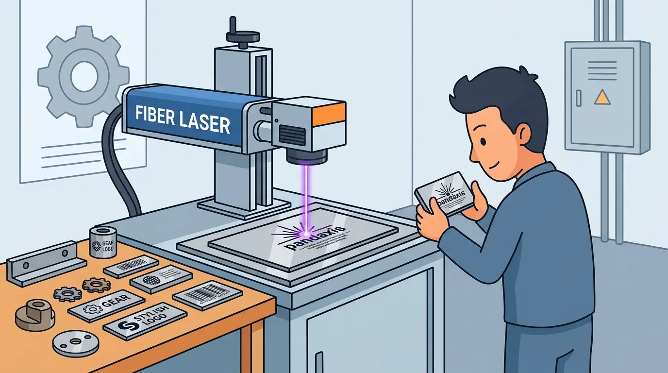
| Standard Fiber Laser | General metal marking and light etching on many common alloys | Strong metal compatibility, good speed, broad industrial use | Less flexible when the job demands very fine heat control or wider visual mark variation |
| MOPA Fiber Laser | Stainless marks, anodized surfaces, finer cosmetic control, mixed mark styles | Better pulse control, wider process window for dark marks and cleaner visual tuning | Usually costs more than a basic fiber setup for buyers who only need simple ID marking |
| UV Laser | Heat-sensitive parts, fine features, delicate coatings, tighter cosmetic demands | Lower thermal impact, cleaner work on sensitive layers and small details | Often slower and harder to justify if the line mainly runs standard metal IDs |
| Green Laser | Reflective metals and specialized high-contrast work on difficult surfaces | Can make sense when reflective materials narrow the process window too much for other choices | More specialized, so the business case should be tied to a real material challenge |
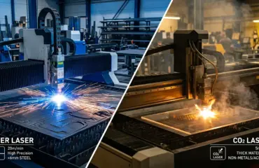
| CO2 Laser | Coated metals, treated surfaces, or workflows using marking compounds rather than bare-metal etching | Useful when the real process is surface treatment on top of the metal rather than direct bare-metal interaction | Not usually the first choice for direct etching on bare metal parts |
In practice, standard fiber and MOPA fiber systems cover much of the industrial discussion for metal identification and shallow etching. UV and green sources become more relevant when heat sensitivity, surface finish, or reflectivity shrink the usable process window.
Match the Source to the Metal and Surface Condition
Metal type matters, but surface condition often matters just as much. A polished stainless housing, a cast aluminum part, an anodized panel, and a plated brass fitting can behave very differently even when the buyer describes them all simply as metal.
| Material or Surface | Source Logic That Commonly Fits Best | Main Selection Caution |
|---|---|---|
| Stainless Steel | Standard fiber for routine identification; MOPA fiber when dark cosmetic marks or more visual control matter | A good sample mark does not guarantee the same contrast across all finishes |
| Carbon Steel | Standard fiber often handles everyday marking and light etching well | Oxidation, scale, and surface preparation can widen or narrow the process window |
| Bare Aluminum | Fiber is common, but process control matters more because visual consistency can shift quickly | Surface variation can make marks look less stable than expected |
| Anodized Aluminum | MOPA or UV can become more attractive when appearance control is a priority | The mark result depends heavily on whether the goal is contrast, color shift, or layer interaction |
| Brass and Copper Alloys | Green or carefully tuned fiber-based approaches can make more sense when reflectivity becomes the real issue | Reflective surfaces can punish weak process control even if the sample part looks acceptable |
| Painted, Plated, or Coated Metal | Source choice should follow the coating behavior first, not just the base metal | Buyers often assume they are etching metal when the real job is controlled top-layer removal |
The safest way to evaluate source fit is to test the actual production finish, not a generic sample coupon. A source that performs well on raw stainless may behave differently on brushed, polished, bead-blasted, plated, or coated versions of the same part family.
Do Not Ignore Heat Input, Contrast, and Edge Cleanliness
Source selection is rarely just about whether a mark appears. It is about whether the mark stays readable, repeatable, and commercially acceptable under production conditions.
Factories should pay close attention to:
- Heat Sensitivity: Thin parts, finished housings, and cosmetic surfaces often punish excessive thermal input.
- Contrast Stability: A traceability code that scans on one batch but struggles on the next is a process risk, not a cosmetic inconvenience.
- Edge Definition: Fine logos, small text, and dense codes often reward better pulse control more than brute-force output.
- Rework Exposure: If the wrong source leaves inconsistent marks, the cost shows up in inspection delays, scrap, or manual retouching.
- Downstream Fit: Some parts go directly to coating, assembly, packaging, or regulated traceability checks, so mark quality affects more than the marking station itself.
This is one reason many buyers move beyond a basic source comparison and start thinking in terms of process window. A source with a larger usable window is often more valuable than one that only produces the best-looking result under narrow settings.
Consider Throughput, Changeovers, and Future Part Mix
The right source for a single part family is not always the right source for a real factory schedule. Buyers should look at production mix, not just the current flagship job.
Questions worth asking include:
- Is The Line Mostly Running One Stable Part Family or Frequent Changeovers?
- Are Marks Small And Fast, or Large Enough That Fill Time Becomes a Bottleneck?
- Does The Cell Need Cosmetic Flexibility, or Only Reliable Utility Marking?
- Will The Factory Add More Reflective, Coated, or Heat-Sensitive Parts Later?
- Is The Real Bottleneck The Laser Cycle, or Loading, Fixturing, Verification, and Handling?
If the operation mainly runs routine industrial IDs on common steels and aluminum parts, a standard fiber source may remain the most practical choice. If the same line must handle darker stainless marks, more cosmetic branding, or more variable surface behavior, a MOPA-based source often earns attention because it gives the process team more room to tune quality without immediately changing machine class.
When Mixed Materials Change the Buying Decision
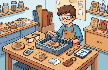
Some buyers use metal etching as the starting requirement, then realize the workshop also handles non-metal parts such as acrylic panels, wood components, layered signage, or branded accessories. That changes the planning logic.
In those cases, it is usually better to separate metal-focused source selection from non-metal laser processing rather than forcing one platform to cover both jobs poorly. If the same facility also evaluates wood or acrylic workflows, those applications usually sit closer to dedicated laser cutters and engravers than to a source chosen specifically for metal etching.
That is an important buying discipline: choose the source around the primary production physics, not around the hope that one machine label will solve every material category equally well.
A Practical Source-Selection Checklist
Use a short decision sequence before narrowing the machine shortlist:
- Define The Exact Mark Type: Surface mark, dark anneal, shallow etch, coating removal, or deeper engraving.
- Group Real Parts By Surface Condition: Raw, polished, brushed, anodized, coated, plated, or reflective.
- Check The Smallest Feature and The Largest Filled Area: Fine codes and broad logos stress the process differently.
- Identify Heat Sensitivity Early: Thin parts and cosmetic finishes can eliminate some source options quickly.
- Test Scanner Performance, Not Just Visual Appearance: Production value often depends on readability, not only contrast by eye.
- Evaluate Changeover Frequency: Stable high-volume work and varied short-run work do not favor the same process window.
- Size the Source Around the Future Mix, Not Just Today’s Sample: Short-term fit can become a limitation if materials or finish demands broaden.
Practical Summary
The best laser etching machine for metal is usually the one whose source matches the actual mark result, surface behavior, and production mix, not the one with the broadest marketing language. Standard fiber sources often make sense for routine industrial marking and light etching. MOPA fiber sources become more attractive when the workflow needs wider control over appearance and heat input. UV and green sources earn their place when part sensitivity or reflectivity makes the process window too narrow. CO2 belongs in the discussion mainly when the job is really coating interaction rather than direct bare-metal etching.
The practical rule is simple: define the mark, define the surface, define the bottleneck, and then choose the source that gives the line a stable process window rather than the most generic promise. That is what keeps a metal etching investment useful after the sample plate leaves the table.