In metal engraving, the wrong power choice rarely fails on the sample plate. It fails later, when cycle times stretch, fine codes lose clarity, thin parts pick up too much heat, or the factory pays for output the line never actually uses. That is why matching a laser engraver for metal to the material is not just a wattage decision. It is a process decision tied to mark type, part geometry, production speed, and surface behavior.
Many buyers also use “laser engraver” as a broad market term even when the real job is marking, etching, annealing, or shallow identification. That distinction matters. The same metal can need very different power levels depending on whether the goal is a dark traceability mark, a shallow logo, or deeper material removal.
Start With the Mark Result Before You Start With the Material
The fastest way to oversize or undersize a system is to begin with the metal name alone. Stainless steel, aluminum, brass, or tool steel only tell part of the story. Buyers should first define what the mark needs to do in production.
| Mark Result | Typical Production Use | Power Tendency | What Usually Changes the Decision |
|---|---|---|---|
| High-Contrast Surface Mark | Serial numbers, data matrix codes, product IDs | Lower to moderate power is often enough | Code size, scan reliability, cosmetic expectations |
| Shallow Engraved Mark | Logos, fixture IDs, durable visible text | Moderate power is commonly preferred | Required permanence, mark area, cycle time |
| Deeper Engraving | Tooling IDs, molds, harder-wearing permanent marks | Higher power becomes more attractive | Required depth, pass count, throughput target |
| Large Filled Graphics | Nameplates, broad logos, dense content | Higher power often helps when speed matters | Total filled area, shift volume, automation level |
| Fine Microtext or Small Codes | Compact components, dense traceability | Controlled power matters more than raw power | Spot quality, focus consistency, surface condition |
This is why two factories working with the same stainless steel part may need different laser power. One may only need readable contrast for a scanner. The other may need faster cycle time on a larger filled logo or a more aggressive engraved result.
Why Material Still Matters in the Power Decision
Once the mark objective is clear, the material and surface condition start to shape how much power is practical. The important point is that material affects the size of the process window, not just the headline power requirement.
| Material or Surface | Common Objective | Power Tendency | Main Selection Caution |
|---|---|---|---|
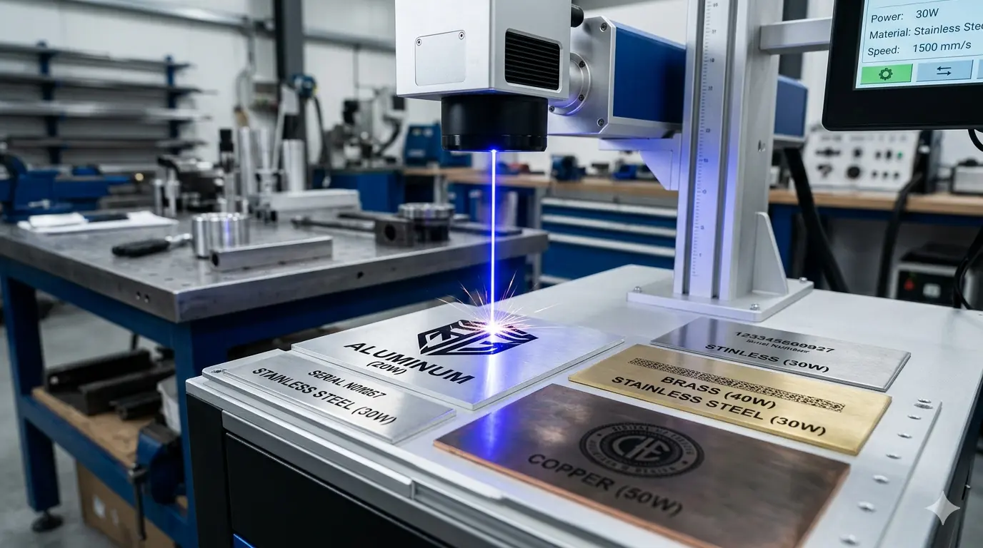
| Stainless Steel | Contrast marks, traceability codes, durable IDs | Lower to moderate power often works for surface marks; higher power helps when depth or speed matters | A good-looking sample does not guarantee reliable scanner performance at line speed |
| Aluminum | Logos, serial numbers, branded components, coated-part identification | Moderate power is often enough, but surface condition changes the result quickly | Bare, anodized, coated, and cast surfaces can behave very differently |
| Tool Steel and Hardened Components | Mold IDs, fixture marks, durable workshop identification | Moderate to higher power is more commonly justified when permanence and faster engraving matter | Harder materials can push buyers toward more passes or more power margin |
| Brass and Copper Alloys | Logos, tags, visible part IDs, specialty marking | Power alone is rarely the whole answer; tighter process control is usually needed | Reflective surfaces and heat flow can narrow the usable process window |
| Painted or Coated Metal | Coating removal, exposed-contrast identification, top-layer marking | Power should match the coating-removal goal, not just the substrate | Too much power can damage the finish outside the intended mark |
The surface condition often matters as much as the metal family. A polished part, a bead-blasted part, a painted enclosure, and an anodized component can all respond differently even when the base metal is similar. That is why real-part testing is more useful than generic material assumptions.
When Lower or Moderate Power Is Usually the Better Fit
Lower or moderate power is often the better choice when the factory mainly needs readable identification rather than heavy material removal. In many plants, that covers most day-to-day metal marking work.
This is commonly true when the application involves:
- Serial Numbers And Traceability Codes
- Compact Logos Or Part IDs
- Small Components With Limited Marking Area
- Cosmetic Marks Where Edge Definition Matters
- Job Shops Running Frequent Changeovers Instead of Long Repetitive Batches
In these cases, the workflow benefit usually comes from control rather than brute force. A stable process window, cleaner fine detail, and easier heat management can matter more than chasing the largest possible watt number. That is especially true when operators load parts manually or when inspection and data verification take longer than the mark itself.
If the marking station is not the real bottleneck, jumping to a higher-power system may add cost without changing total cell output very much. The factory may gain more from better fixturing, cleaner part presentation, or stronger software-to-inspection workflow integration.
When Higher Power Actually Starts To Pay Off
Higher power starts to make sense when the factory can clearly show that the marking process itself is limiting production. That usually happens in more demanding workflows, not in routine metal identification alone.
Higher power is more often justified when:
- The Line Needs Shorter Mark Time to Keep Pace With Upstream Production
- The Mark Requires More Depth Rather Than Surface Contrast Alone
- The Marked Area Is Large Enough That Fill Time Hurts Throughput
- The Factory Runs Longer Shifts With Heavier Duty Cycles
- The Same Cell Must Handle A Wider Range of Tougher Metal Jobs Without Constant Compromise
In those cases, higher power is not a prestige upgrade. It is a throughput tool. It can reduce pass count, shorten filled-mark cycle time, and create more headroom when volume rises. But the business case only holds if the rest of the cell is ready. If loading, unloading, focus setup, or verification still slows the process down, the extra power may spend much of the shift waiting on the same old bottlenecks.
Why More Power Does Not Automatically Mean Better Metal Marks
This is where many buying decisions go wrong.
Higher power can improve speed, but mark quality still depends on beam quality, optics, pulse control, scan strategy, part stability, and surface preparation. A system with more power but weaker process discipline can easily produce worse results on fine text, dense codes, or cosmetic logos than a more moderate system that is tuned properly.
Common problems that show up when power is oversized for the job include:
- Excess Heat Input on Thin or Sensitive Parts
- Reduced Crispness on Small Text or Dense Codes
- Harder-To-Control Cosmetic Consistency
- Unnecessary Cost for Capacity the Plant Does Not Use
- A Narrower Setup Window for Daily Operators
That is why buyers should treat higher power as one variable inside a controlled process, not as proof of a universally better machine.
The Variables That Often Matter More Than Raw Power
Even in metal applications, raw power is only part of the selection logic. Several other variables often decide whether the result is commercially useful.
- Beam Quality And Spot Size: Small features, compact codes, and clean line edges often depend more on how tightly the mark can be controlled than on how much power is available.
- Pulse Control And Process Tuning: Different metal surfaces respond differently to frequency, pulse duration, scan speed, and hatch strategy. Power without tuning usually creates inconsistency.
- Surface Condition: Oxide layers, coatings, polishing, blasting, and anodizing can all change how the material responds.
- Part Presentation And Focus Stability: If the part does not land in the right position every cycle, extra power will not fix poor repeatability.
- Mark Area And Fill Density: Large logos and filled fields change the economics more than tiny serial numbers do.
- Whole-Cell Throughput: Manual handling, barcode verification, and software workflow often limit output before the laser source does.
In other words, buyers should ask whether they are solving a power problem or a process-control problem. The answer is not always the same.
A Practical Buying Framework for Matching Power to Material
The most reliable way to size a metal laser engraving system is to work through the application in a fixed order.
- Define The Mark Function. Decide whether the job is contrast marking, shallow engraving, deeper engraving, coating removal, or a mixed requirement.
- Group Parts By Surface Behavior. Separate polished, coated, anodized, blasted, and raw-metal parts instead of treating all metal parts as one category.
- Check The Smallest Feature And The Largest Filled Area. Fine codes and broad logos stress the process in different ways.
- Identify The Real Bottleneck. Confirm whether the cell is limited by mark time, loading time, fixturing, software flow, or inspection.
- Test On Real Production Parts. Use actual part finishes, actual code sizes, and realistic cycle expectations instead of ideal showroom samples.
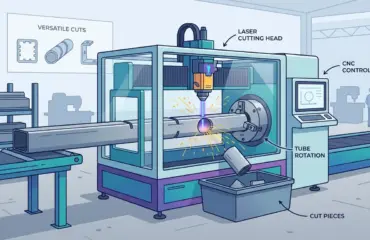
- Keep Marking Separate From Other Laser Processes. If the real requirement is cutting, welding, or cleaning, that is a different machine-class decision, not just a power upgrade.
This framework helps buyers avoid two common mistakes at the same time: buying too little power for a throughput-driven job, or buying too much power for a detail-sensitive marking workflow.
For manufacturers evaluating a marking investment alongside wider factory equipment planning, the Pandaxis product catalog provides a broader view of industrial machinery categories and workflow-oriented equipment selection.
Practical Summary
Matching a laser engraver for metal to the material starts with understanding that power is only useful in context. The right level depends on what kind of mark the factory needs, how the metal surface behaves, how much depth or contrast is required, and whether the real pressure is quality, speed, or both.
For many metal applications, lower or moderate power is fully sufficient when the goal is reliable identification, fine detail, and stable day-to-day control. Higher power earns its place when the workflow truly demands faster cycle times, deeper engraving, larger marked areas, or more production margin. The safest buying logic is simple: define the mark, define the surface, define the bottleneck, and then size the power around that reality instead of around a headline number alone.